Full adder circuit diagram Full adder equation Circuit adder bit diagram logic computing learn let
Given a 4-bit full-adder-based ALU (see diagram), | Chegg.com
Adder circuit construction binary circuits sourav gupta Half using bit adders four adder circuit schematic circuitlab created Let's learn computing: 4 bit adder circuit
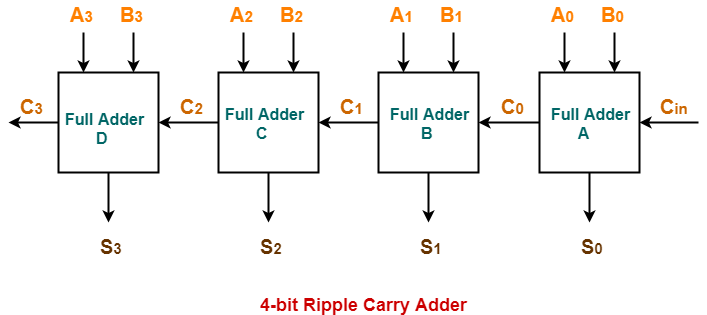
Adder bit parallel four circuit binary diagram logic subtractor digital block example geeksforgeeks detailed discussion
Let's learn computing: 4 bit adder/subtractor circuitFull-adder circuit, the schematic diagram and how it works – deeptronic Adder theorycircuit4 bit parallel adder circuit diagram.
Adder vhdl 8bit compile simulate waveform verifyAdder half adders 4 bit binary adderAdder truth logic half sumador gates binario inputs datasheet combination suma microcontrollerslab.

4-bit adder-subtractor in digital circuit
Adder circuit logic schematic circuitglobe circuits fig sum compressor robhosking combinational shownWhat is half adder and full adder circuit? Using bit half adders four circuit logic digital circuitlab schematic created electronicsAdder bit description half introduction hardware language ppt powerpoint presentation gate input module level slideserve.
4 bit adder subtractor circuit diagramAdder logic half implementation Adder bit using circuit adders four half circuits implementation watson just single box into latech eduDigital logic.

Adder circuit diagram schematic bit works figure
😊 four bit parallel adder. 4 bit binary adder circuit / block diagramAdder circuit combinational ha sequential 4 bit full adder circuit, truth table and symbol. implement 4 bitAdder subtractor bit circuit add sub overflow questions complement logic detection carry addition designing control zero line digital find.
3 bit full adder4 bit adder subtractor Cs 3410 spring 2018 lab 1Full adder logic diagram.
Cd4008 4-bit full adder ic pinout, working, example and datasheet
Full adder circuit: theory, truth table & constructionBinary full adder circuit diagram Cd4008 4-bit full adder ic pinout, working, example and datasheetGiven a 4-bit full-adder-based alu (see diagram),.
Digital logicFull adder in digital electronics Digital logicAdder bit logisim using circuit complement alu cs unsigned lab1 lab courses labs cornell edu build create re ta sub.

Adder circuit gate adders expressions implement two
Full adder circuit diagramCircuit diagram full adder subtractor Vhdl tutorial – 21: designing an 8-bit, full-adder circuit using vhdlAdder binary bit circuit rtl truth table example understand will need register adders use discuss details.
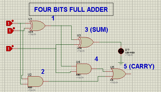
Adder subtractor bit circuit ripple carry diagram logic using project build only digital computing learn let its single indie electronics4-bit full adder using logic gates in proteus 2 bit full adder subtractor circuit diagramCombinational and sequential design of a 4-bit adder. (a) ha circuit.

[diagram] logic diagram 4 bit adder
Adder logic wiring t1 .
.


Given a 4-bit full-adder-based ALU (see diagram), | Chegg.com
4 Bit Parallel Adder Circuit Diagram - IOT Wiring Diagram

VHDL Tutorial – 21: Designing an 8-bit, full-adder circuit using VHDL

Binary Full Adder Circuit Diagram - Circuit Diagram

😊 Four bit parallel adder. 4 bit Binary adder circuit / block diagram

Full adder in digital electronics - tutorialsinhand.com